29 February 2012

SolidWorks and Inkscape (27.2.12)


Today in class Oscar introduced us to two design programs: SolidWorks and Inkscape.  SolidWorks is a popular tool to design in 3D.  We started by following one of SolidWorks' tutorials, but because of technical difficulties surrounding operating in Windows on a Mac, it took around 35 minutes before SolidWorks ran properly and didn't crash. The program itself is intricate, but allows the user to design some amazing projects.  Here are a few examples from SolidWorks:

 
https://plus.google.com/100923600711217681276/posts/N4qQKD7EegE

 
pcwin.com

 
solidsmack.com

After working for a little while, Oscar introduced us to Inkscape, a program great for both 2D and 3D designs.


http://www.tigert.com/2005/10/27/free-software-for-designers/

 http://www.cartographersguild.com/showthread.php?1392-Isometric-map-elements-for-Inkscape-(SVG)

Our challenge was to design a carabiner that would be made using the Laser Cutter.  We decided to work in Inkscape, since it's interface is great for designing in 2D.  More on my design will come in the next post!

26 February 2012

Springs! (23.2.12)

Today we created virtual springs.  Oscar began by having us consider this circuit below, where K is a variable we define.


We abstract the circuit from the previous image to become this:


Next, Oscar explained more information about our system that we can derive by knowing torque.:

Torque proportional to angular speed is friction.  
An object exposed to friction slows down.  
Torque proportional to angular position is a "spring." 

 We considered this formula:


 The greater the angular position of the pendulum, the greater the torque causing it to swing back.


Next Oscar introduced us to two important formulas:


The rate of change of position is angular speed.


The rate of change of speed is acceleration.


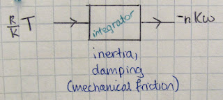
We want torque proportional to position such that we make a spring.  But how do we go from speed to position? (ω → θ)  We integrate it.  A capacitor integrates current to produce a change in voltage.  (flashback to calculus 101: the integral of speed is position).


Then Oscar showed us this circuit....


... and explained this abstraction:


After all that, it was time to get to the breadboards.  We started by creating this:


The effect of the virtual spring created this on the oscilloscope:


We had fun with the settings, and were able to have the oscilloscope measure the output like this (looks like a galaxy, no?):


Using Legos, we created a pendulum that demonstrates the properties of a spring:

17 February 2012

Motor Model (16.2.12)

Today we discussed motors.  Oscar showed us this abstraction to represent a motor:


Next Oscar showed us this abstraction, with a lever on which we can exert torque:


To control torque, control current.

We can calculate the torque in the system above using this formula:


Next Oscar showed us a complex circuit with a current driver and explained the formulas that allow us to calculate the voltage and resistance at various points in the circuit.  We use two potentiometers (upper right, written in red) and a motor (depicted in an abstraction shown as a circle with little nibs coming out of it.  We can calculate the voltage of the motor as being the resistance times energy of the motor plus the potential difference of the voltage).  This particular circuit was hard for me to grasp completely.


We went to our breadboards and connected Lego motors to an op-amp.  When we have negative feedback, a virtual ground is created (as you can see in the picture above).  We were able to control the motor's direction and rotational speed with the potentiometers.  We added a giant Lego wheel to the end.  This reminded me of our first day in engineering class where Oscar had an example for us showing a wheel and motor attached to an oscilloscope.


The last thing we did in class was calculate the voltage across this circuit.  I'll let the picture below explain it:


15 February 2012

Negative Feedback (13.2.12)


Today in class we learned about negative feedback.  To understand this, we calculated the value of Vo for the following circuit:


Because the value of A is large, it leads to a more simplified model, saying that if:

V+  > V- then Vo = 12V
V+  < V- then Vo = -12V

When we add positive feedback to the OP Amp, like this:


Then it exhibits hysteresis and if:

V- < 6V then Vo = 12V
V-  > -6V then Vo = 12V

This might sound familiar, because it is an example of the Schmitt trigger we learned about last week.


So that was when we added positive feedback.  But let's say we have this:


Then V- = Vo/2 and if
V+ < 6V then Vo = 12V
V+  > -6V then Vo = 12V

Which can be graphed like this:


When -12V < Vo < 12V, then V+ = V- .  We already established that V- = Vo/2, but since V+ = V- we can replace V- with V+ and solve for Vo, so that Vo= 2V+ .  When we graph this, we find a line like this:


With positive feedback, we don't see the vertical blue line , but with negative feedback, we do.  The vertical green line is the jump from -12V to +12V.

09 February 2012

Capacitors (9.2.12)

Today Oscar introduced us to capacitors.  Capacitors accumulate current and express it as voltage.  We calculate it using this formula:

A sample capacitor is shown below:


Since our circuit contains a resistor, the capacitor will charge until there is a 0 voltage difference between the ends of the resistor.  The capacitor charges faster when there is a greater voltage difference.  If we graph the voltage over time, we see the voltage starts high, but approaches 0 and stabilizes.

As you can see here, in a more detailed version of our circuit shown above, the amount of current flowing clockwise becomes smaller.


We then tried working with capacitors on our breadboards, and worked with this circuit: 


Oscar gave us a pictorial version as well, which looks like this: 


By adding a capacitor to our circuit, we made an oscillator!


We added a speaker (the cylindrical cone with the big G) so that when we manipulated the potentiometer, a different pitch came from the speaker.  The end of class was a lot of fun when we all had speakers going at various high, annoying pitches!


07 February 2012

Abstraction and Hysteresis (6.2.12)

Our next lesson included exploring the art of abstraction--or dealing with a concept or

An example of the flow of abstraction would be as follows:

Designing at the circuit level
Creating digital gates/ analyzing digital signals
Building systems of digital gates
Creating modules
Creating microprocessors and operating in assembly languages
Programming with high level languages to create programs

When we work at a higher level, we do not need to fully understand the levels below us (or in my particular chart, above us) to successfully work at our particular level.  For example, it it not necessary for me to understand logic gates in order to program in C++.  I can skip over the lower level information, by using abstraction, thereby allowing me to work only with the information needed for my target level.

Next we reviewed resistors, which are used to measure current.  The voltage in a resistor can be measured by V=Ri and the current flowing over a resistor is i=V/R.  Current in circuits does not accumulate and just because you put force on something, doesn't mean you are necessarily doing work.

In our experiments, the OP Amp operates so that the voltage only exists at either of two extremes: -12V or +12V.  This means, turning the nob on the potentiometer creates no change in the oscilloscope until it is turned the maximum way in either direction.  We understand the voltage using this formula and drawing these conclusions:


Next Oscar explained hysteresis, using the analogy of bending a credit card.  In the following diagram we see the card can bend right when positive force is applied and can bend left when negative force is applied.


In this following picture, we see the effect of adding positive or negative force on the card depending on the card's starting position.  This experiment explains that the card can only exist as either bending left or right, and although there is a range of force that can be applied, change only occurs when enough force is applied and the card suddenly snaps to the other position.  Weak force in either direction will not change the position of the card.


We graph a hysteretic comparator like this:


The straight green line is the hysteretic comparator, and the blue squiggly line is the potentiometer being turned to adjust the voltage.  What we see here is that the voltage can fluctuate freely until it reaches +6V or -6V, which triggers the hysteretic comparator to jump from +12V to -12V depending on its previous position.  Once the voltage hits +6V or -6V, it doesn't matter if it hit that value again or surpasses it; the only way to change the voltage of the hysteretic comparator, if the voltage hit +6V, for example, would be for the voltage to drop down to -6V.

We can prove this by measuring the voltage as (V+-V- ).  This  hysteretic comparator is an example of the Schmitt Trigger, which is illustrated like this:


Our circuit looks like this:


And here we understand how hysteresis changes our circuit:

05 February 2012

Voila Breadboards! (2.2.12)

To further understand current and get some hands-on experience, we experimented with breadboards.  A breadboard is an apparatus that allows for experimenting and tinkering with electric circuits.

Some of our tools include the breadboard itself, a DIN Jack, OP Amps, various colored wires, jumpers, potentiometers, resistors and capacitors.


First, we plug the DIN (Deutsches Institut für Normung) Jack into the breadboard and use wires to connect the prongs of the DIN to rails on the edge of the breadboard, establishing specific rails as having -12V, 0V, 5V and 12V (volts).


In the following picture, blue and black wires have directed the flow of electricity from the DIN (which is now plugged into an oscilloscope) to each rail.  We test the voltage of the farthest rail, for example, (which should be +12V) by sticking one end of a wire into an open cell in the rail, and touching the other end with the probe...


... which measures the velocity and the osicllosope reads 12 above the dotted line (ground).  Success!


We then incert two 10 KΩ (kilo Ohm) potentiometers (POT), which have three prongs, each alligning to an indivudual row.  The first prong is connected by a wire to the +12 rail, and the third prong is wired to the -12V.  By chooseing these two parameters, our potentiometer has a range of -12 to +12.  The middle prong is at ground, or 0V, when the arrow pointer on the top of the blue POT is at neutral, which in this picture, appears pointing to the left (the farther of the two POTs in this picture is in neutral).  The closer POT has been turned about 80 degrees from the neutral potition, giving the voltage flowing through the probe to the oscilloscope a charge around -6V.


Sometimes, if oscilloscope does not provide the reading we anticipate, but we are confident in our wiring on the breadboard, we can troubleshoot by auto-setting the probe, which produces this on the oscilloscope: