30 April 2012

Our Book Grows (30.4.12)

Today we worked on creating a sturdy base for our pop-up and decided once and for all to make more pages.  If we can get it done in time, we ideally would like to create one page for each installment in the Harry Potter series, but at the moment decided that, in addition to our completed page shown below, Erin, Kelsey and I would each work on one page so that we will have at least four in the end.


Our completed page illustrates the final battle between Harry and Voldemort (7th Book) and uses LEDs to simulate the spells being cast my each wizard.  You can see the unlit LEDs sticking out near the fold in the Hogwarts Castle.  This is, however, only a prototype; we plan to cut each page using various colors of cardstock and add more illustration on each page.

Erin is working on a page with a basilisk (2nd Book) whose eyes light up and are controlled by a photo resistor such that the user of our pop-up can turn-off the basilisk's eyes with their finger.  Kelsey is working on a hippogriff with movable wings (3rd Book) which will be a page focusing more on pop-up design/ paper engineering.  My page will show Bellatrix with a movable arm so that she can touch her wand to her dark mark.  On the other side of the page we will have a light-up dark mark in the sky.

Our entire book will be supported by a cardboard lid we found in the engineering lab.  The flat top of the lid will have the pages fastened, and our circuits will pass through the lid to the back where we attached two breadboards to handle all our circuitry.  I exacto-knifed a hole in the side so that our power supply can pass through the side (we chose to do this over attaching eight AA batteries, which is what would have been necessary to power our pop-up).

Shown below is our circuit with two red and green bicolor LEDs which we will attach to our Hogwarts pop-up in the final scene between Harry and Voldemort.


For anyone unfamiliar with the Harry Potter series, my page features Bellatrix and the dark mark tattoo as seen below:

http://heidihastings.deviantart.com/art/Bellatrix-190292381

The Dark Mark in the sky:

http://images4.wikia.nocookie.net/__cb20110401033142/harrypotterwiki2/images/3/3d/Dark_Mark.jpg

Buckbeak the Hippogriff:

http://darksuperpuffyclouds.webs.com/photos/null/buckbeak.bmp

The Basilisk:

http://www.fearnet.com/eol_images/Entire_Site/20101018/HP02_basalisk.jpg


26 April 2012

Silhouettes and Stained-Glass (26.4.12)

Today I worked on creating the pieces of our pop-up, while Erin and Kelsey worked on designing the circuits for our flashing lights.  Once again  Bézier curves saved the day, making it almost effortless to design silhouettes of Harry and Voldemort.

The snapshop below shows the completed Harry figure and the beginning of Voldemort.


I start by creating a bunch of straight Bézier curves in a rough outline of what I want the figure to look like.  Then I make each node curved and make the curves on the left and right of each node independent from each other.

We decided to add a scar and the outline of glasses on Harry and added an eye on Voldemort.  After that, we cut the design out of card stock with the laser cutter.  We changed the power to 10%, the velocity to 130, and made the frequency of the laser 1000 instead of 10000, which is it's usual setting.  The first try only engraved the paper, so we upped the power to 20% and came out with these two figures below:


[ I leaned them against my computer screen. That's Erin and I in the background :) ]

Our final figures will probably be cut from black card stock so that they better resemble silhouettes, but for now, creating these prototypes was exciting!  This weekend I will be designing a Hogwarts castle and will begin engineering the other elements of our pop-up.

In addition, I was working on a side project to create a stained-glass inspired window decoration to give as a gift for a good friend.  I used an axonometric grid and Bézier curves once again, and used layers to make a preliminary sketch and a final product, which is shown below.


Cutting it was a little difficult because not all the pieces came out cleanly, but after some carefully placed pressure on the pieces and some clean-up work with the filer (we don't have sand paper in the lab, oddly enough), I'm fairly pleased with the result (and hopefully my friend be will too!).


23 April 2012

Manning the Engineering Table (23.4.12)

Our class today fell during Wellesley's Spring Open Campus for accepted students, and during class was a fair in the science center in which each department had a table.  There was also an engineering table (next to physics and astronomy!) so Erin and I decided to bring up a bunch of cool examples of laser cut, 3D printed, Lego-built and electronic examples of the cool things students can do in the engineering lab.

Some of these cool things included a 3D printed gear heart, like the one below:

http://www.rapidreadytech.com/wp-content/uploads/2012/03/Gear-Heart.jpg

A few members of my particle zoo were there as well:


These particle zoo figures were based on the stuffed versions of the Standard Model made here: http://www.particlezoo.net/
Each particle was laser cut and I used white-out to make the faces.  On the back is the name of each particle plus it's mass, spin, charge and symbol.

Erin and I answered many questions about engineering possibilities at Wellesley, MIT and Olin.  Since Erin's taking a class at Olin next year and I'm currently taking a Course 16 (AeroAstro) class at MIT, we were able to cover all the engineering bases!  I even had a student text me saying that my input on engineering here was one of the deciding factors in her choosing Wellesley! (I also sent about 5 very long facebook messages to prospies about engineering and research at Wellesley, and two more said my input really helped).

Next class Erin, Kelsey and I will get down to business with our final project, a Harry Potter themed pop-up book!

20 April 2012

Slight Complications (19.4.12)

Today Erin, Kelsey and I finished soldering the rest of our circuitry and tried putting it all together with the batteries.  We used small metal plates to connect the batteries in a series, but had trouble keeping the plates in the right position.  Because our flashlight is made of delrin and most glues won't stick and we found ourselves having to use regular old scotch tape to keep the metal plates in place.  This is not a satisfactory solution (for me, anyway) and I still want to experiment with other techniques.

If we held everything carefully in position with our hands, then we were able to get the LEDs to light.  The problem was, we had trouble keeping the batteries flush against the metal.  A few times we achieved this, but then if we tried to squish the rest of our circuity inside, everything shifted around a little and the LEDs would not light.  Although everything in principle fit within our case, when we actually tried to close it, we had trouble positioning the batteries first.  We tried closing it a few times and used scotch tape to keep everything in place, but it just wasn't working.

After messing with it a few times, some of the solder connecting the resistors to the switches broke off, so I worked for a great chunk of class today re-soldering much of the circuitry.  The LEDs still worked after the soldering fixes, but when we tried to combine it with the batteries and put it in the case, it all just wasn't coming together.

We originally were using metal plates, but then we experimented with creating coils stretched to look like springs instead.  I was able to make these using pliers and my hands, and they looked good, but did not fix our problem.  The batteries would slide off the tips of the coils.  Oscar suggested taking a plate of metal, and instead of having it lay flat against the bottom of our lantern case, like we originally had done, we bend the metal into a sort of staple, which could take some pressure from the batteries and offered much more surface area than a coil.  Again, using this method, our LEDs lit, but we couldn't consistently get our lantern to work when we closed up the case.

We're going to start our final project next week, so unfortunately we didn't get our lantern in good working shape in time.  We did have the most complicated circuits and three LEDs (the other groups used one).  It's possible our ambition held us back, but either way, we learned an important lesson in engineering: not every project will go as planned, and problems will arise along the way, but as long as you work together, keep a clear vision of your project in mind, and consider all possible solutions, you will, in the end, learn much more about engineering than if you had an easy project.  I'm actually kind of glad one of our projects didn't work, because then I know we really challenged ourselves.  Either way, I can't wait to get working on our final project!

13 April 2012

Putting the Solder to the Metal (12.4.21)

I apologize that my titles are so cringe-worthy.

Getting back to the matter at hand, today I soldered the majority of our circuit.  If I haven't said this enough already, soldering is so much fun!!  Liquid metal is really beautiful.


I started by soldering the LEDs to the resistors and trimming the lengths.


Next the LEDs and resistors were soldered to the switches.

One rather humorous thing I thought I'd mention are the two diagrams Erin and I used to explain the inside of our lantern.  This is Erin's:


And this is mine:


 As you can see, I attempted a 3D view of our lantern from the bottom, looking towards the top.  I don't know how understandable it is to others, but it made sense to me and I referenced it often as I finished soldering our circuits.

Also, I don't think I've uploaded any really cool laser printer images in a while, so I thought I'd share these two:


09 April 2012

Getting to Work (9.4.12)


We decided to modify our box from being square to being an octagonal prism (go eight sided-things!) with living hinges to make the eight sides.  We still used my idea of creating a layer in the middle with holes to hold the batteries.


Here's a picture of the sides of the lantern, designed by Kelsey out of white delrin, photo borrowed from Erin :)  We made three opening for the switches (which you can see in the pictures farther below).  Note the living hinges and eight sides.


The picture above shows our octagonal prism with the battery layer and batteries inside.  Photo also courtesy of Erin.


We discussed what we wanted the top of the lantern to look like.  We considered either cutting squares that fit the entire LED or cutting just a hole big enough for the tip of the LED.  We found cutting the small holes worked just fine, and produced a nicer glow.


Next we took our double resistors and I soldered them together, which was a lot of fun.  Above you can see the three stages of our resistors:

  1. twist the wires together
  2. solder the resistors together and cut off one of the wires on each end
  3. flatten the remaining ends
Later, once we have the body of our lantern constructed and have our LEDs in position, we will trim the length of each resistor.


Next we tested our newly soldered resisters, and the outcome looked bright! (pun very much intended).

Also today in class, Oscar showed us the Lytro!!  It was really exciting actually holding one.  We experimented with taking a few pictures.  The quality isn't great (the example photos on the website were much more impressive than the ones we took (I'm not surprised at all by this)) but it was fun either way!


Oscar also gave us these little kits to make on our own.  If you go to the Mad Scientist Hut website, you can see a listing of all the projects you can make with just these few parts.

05 April 2012

Starting Our Next Project! (5.4.12)

Today we start our second project!  We are going to make lanterns in groups and divided into two groups of two and one group of three.  I am in the group of three working with Erin and Kelsey.  First Oscar reviewed with us the circuitry necessary to power LEDs with batteries.

We decided to make a circuit with three differently colored LEDs and three switches to control each LED.  This is the circuit we came up with:


We decided on creating a square base with three AAA batteries (although the bottom of the image says 2 batteries, we realized we would need three for our circuit). 

I proposed that we hold the batteries within the base by creating an inside panel with one hole for each battery.  This panel would secure the batteries between two of the walls.  It's a little hard to draw, but here's a rough representation of my idea:


Here are more of our sketches:


The LEDs would stick out a hole in the top of the box.  We could then have four magnets at each corner which would allow us to attach various "tops" or "shades" above the light source to make it glow, or manipulate its direction.  We also thought of lining this "shade" with aluminum foil to add to the brightness.

Next we looked at what materials were available to us and decided on using three four-prong LEDs; one red, one blue, one yellow.  We also decided to have a switch correspond to each LED, so we can turn each LED on individually or combine them.  Our LEDs will be parallel to each other, but this is ok because each LED will have its own resistor.

We got to work with our breadboards, after making sure each LED was oriented correctly, came out with this:


Tangent: We also checked out this cool product by Bleep Labs:


http://bleeplabs.com/

03 April 2012

Presenting our Boxes (2.4.12)

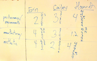
Today we presented our boxes and rated each other on various factors including aesthetics, manufacturing, performance, and whether or not it fulfilled the requirements.  Because my final green box wasn't finished, I used my completed white prototype (I felt the green box would be prettier but my classmates liked the white box just as well).

It was interesting seeing just how diverse our boxes were, and what materials we choose to use.  My box used the most different materials (acrylic, contact paper, hot glue, magnets, tape) whereas some boxes were just acrylic.  My box was also the only non-cube-shaped box and the only one to incorporate magnets.  While my classmates made boxes in which the sides met at 90 degree angles, I had to find a way to make my sides come together sturdily.  My box ended up being quite sturdy.

Another interesting thing about my project is that I started with an original plan (I want to make an octahedron!) and I followed through and accomplished that goal, with few changes in plans along the way (I suppose you can judge my use of the word "few" by reviewing my other posts, but my concept sketch exactly matches my final product).  This is in stark contrast to some of my classmates, whose final boxes do not resemble their original plans at all.  It was interesting to see how some students completely redid their plans throughout the time we had for the boxes, while I did not modify anything.

When it came to evaluating the manufacturing of my box, I explained that, for me, making this box was really enjoyable.  It's by no means an easy or quick box to make (some of my classmates have boxes where you just laser cut them, fold a few sides, and you're done).  I found that the production of my box requires a certain amount of craftsmanship, care towards detail, and willingness to work with one's hands.  I love projects like this, so making my box was fun for me, but to some of my classmates my box appears complicated and painstaking.


Above are pictures of the white board with our ratings.  Interestingly my box was the only one to get a 1,2,3,4, and 5 in the manufacturing category, meaning that opinion on my box really stretched the full spectrum of possible scores.

In our next class we will be assigned Project #2!