31 March 2012

Starting Octahedron V2.0 (29.3.12)

After completing my first prototype out of white delrin, I went back to the green acrylic and started a final version (I find the green acrylic much prettier).


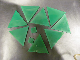
I started by laser cutting the pieces.


There was a long line for the laser cutter in class today, so it took a while before I had these pieces ready to go.

Oscar suggested I try drilling the hole for the nut, so that I could get a more snug fit.  If I was feeling particularly skilled with the drill, I could try drilling only halfway, so that the nut wouldn't bee seen from the outside.


I started by attaching it to a clamp and backing it with wood.  I also had to wait a while because another student was using the drill.


But once I had the drill in my hands (and had some help from Oscar), I made this hole, which is much cleaner looking than the hole in my white prototype.

After making this I got to work attaching the other triangles with contact paper and on monday will go through the same hot glue procedure as last time.

27 March 2012

Completing a Prototype! (26.3.12)

After getting back from spring break, we're hard at work again in the engineering lab!

Where I last left off, I had these three pyramids:


My next task is to combine them to complete the octahedron!

I cut a fresh batch of triangles from white delrin and also cut two squares that would sit at the tips of each triangle.  The little space between the tip and the square would be filled with hot glue.  I lined the sides of the squares with black so that they would blend into the bottom of the pyramids.  Below you can see four triangles attached with contact paper and my two squares.


I attached 7 of the 8 triangles in the formation of the octahedron (the missing one will be the lid).


You can see how they fold together to make the octahedron.


After solidly attaching the sides with contact paper, I attached the lid (also with contact paper) which you can see hanging open.


I drilled a hole in the tip of the lid, and fit a nut inside (I will be putting a magnet inside that tip of the triangle to keep my box closed).


My next task was to fill the bottom triangle tip with hot glue and situate the box inside.  I grabbed some Lego parts from the giant wall of Legos and constructed a base to hold my box when I hot glue.  It worked really quite well!  Maneuvering the hot glue through the three sides of the top pyramid was hard, but since I had already had practice hot gluing squares in the bottoms of my other pyramid prototypes, I was able to put in just enough glue.


 Next I needed to add my magnet.  I put tape on one of the sides and marked where the nut was, so that when I was putting the in, I would position it so that it alligned with the nut (because how sad would it be if I added a magnet but I did not line up with the nut...)

I had a long square that I used to sandwich the hot glue against the tip.  This larger pocket of space for the hot glue and magnet needed a lot more hot glue to fill than I anticipated.  The hot glue kept settling to the bottom so I let it cool in phases.  Once it was filled with enough room for the magnet, I put in my last layer of liquid hod glue and used tweezers to drop in the magnet.  I neglected to realize that the tweezers were magnetic, so once I finally got the magnet free, it turned sideways and began to sink into the hot glue.  I was able to fish it out with the tweezers and came up with a better idea.


I put the magnet on the end of a screw, and held the screw as I added hot glue on either side.  That way I could keep the magnet from sinking and I could position it properly.  I was really quite proud of this impromptu solution since I was working under time (or cooling?) pressure.  Once the hot glue dried, the magnet was sturdily held and I could just pull the screw off.


Here you can see the tip filled with hot glue and my magnet.  I took a triangle of contact paper and used this to cover the hot glue and magnet for a more professional look.


Here you can see the finished version of my prototype!!!

16 March 2012

A Simple Solution (15.3.12)

Where I last left off, I had a completed pyramid of four green acrylic triangles attached on the outside by contact paper.  One glaring problem is that the sides are not secure, and the edges can shift around a little and wobble.  Some solutions involved notches to add a rubber band or wire or use hot glue to fill the gap between the contact paper and the triangles.

While considering options to add stability, I decided to try an alternate strategy with the contact paper.  What if instead of lining the outside of the pyramid, line the inside?

I followed the same cutting procedure as before, except this time arranged the triangles flush against one another.  The following picture is my first attempt at this.  However, when I attached the fourth triangle with the two paper "wings," I made a slight error:


As you probably noticed, my extra wing is attached to the wrong side of the triangle.  Here's my sad attempt at forming the pyramid:


But on the second try, I got it right... 


and repeated this process with the acrylic to make two new pyramids.


An interesting property of the contact-paper-lined triangles is that they can collapse to fold in half.  One drawback to using wood is that not only does the contact paper stick less firmly as it does to acrylic, but the wood begins to splinter.  On one side, I tried hot gluing the paper to the wooden triangle for extra adhesion, which worked well but the glue left bumps under the contact paper.  Since the paper sticks much better to the acrylic I will most likely end up choosing this as my final material, although the wood is certainly pretty.


Next, I decided to experiment with the hot glue gun by filling the tip of each pyramid with hot glue to hold the sides stable.  I cut a small square of acrylic to cover the hot glue, but as you can see, I greatly overestimated the amount of hot glue necessary:


My second attempt was a little cleaner.  This acrylic pyramid is by far the sturdiest.  My next experiment will be to determine the least amount of hot glue necessary to hold the sides steady.


Although the actual engineering needed to create this pyramid is painfully simple, it achieves our objectives of creating a product with a simple design, small number of materials, and easy manufacturing process.  Initially I was worried I was taking the "easy way out" because my product does not require particularly intricate design or cut with the laser cutter and is almost painfully simple.

14 March 2012

To Build A Pyramid (12.3.12)

My main predicament remains: how to connect the triangles?

After creating my triangles with the notches, I brainstormed with Oscar to come up with other strategies.  One material available to us is contact paper, so I decided to experiment with that while also looking for a way to sturdily attach my notched triangles.

I decided to split the octahedron into two pyramids and focus first on creating a sturdy pyramid.  To start, I cut four triangles out of acrylic with the laser cutter.  Next, I traced the pattern of the four triangles on graph paper and cut the same pattern onto the back of black contact paper.

After cutting my first strip of contact paper, I traced the lines with a ruler to ensure my second cut would have straight lines.
The triangles need to be spaced on the contact paper so that there is room to bend.  I wedged an extra triangles between the two I was measuring to ensure I left enough room.
Here are all three triangles on the contact paper.  As you can see, the spacing is not perfect - this is just a prototype so I didn't spend a lot of time positioning the triangles.
My method was to attach three triangles and then attach the fourth with two triangular "wings" that would overlap the adjacent triangles.

One problem that became evident right after wrapping the contact paper around the triangles was the space created between the edges of the triangles and the contact paper.  This space meant the triangles could wiggle and shift, as you can see in the image below.


One solution would be to hold the two triangles at the right angle before putting on the contact paper, and fill the free space with hot glue.

Figuring out how to make a stable structure will be my objective for next week!

10 March 2012

Our First Project (8.3.12)

Today in class Oscar presented us with our first project: to construct a 2in x 2in box by experimenting with the various materials and methods of construction available to us in the engineering lab.  This is our fist time taking the engineering design process into our own hands.  Our project should flow through five process stages beginning with an idea and ending with a testable product.

  1. Concept
  2. Decision Matrix
  3. Experimentation and Feasibility
  4. Manufacturing
  5. Testing

We can (and should) refine, repeat and return to any/all of these stages throughout our project and use trial and error to discover how to best construct a box that will fit within the given parameters:

  • 2 inch sides
  • cube or similar shape
  • 2 fixed sides
  • two movable joints (free or friction joints)
For creating the movable joints, we have these materials available to us to consider:
  • interlocking materials- this would be a friction method of connecting two or more pieces of materials such as acrylic or wood.  Examples would be zipper-like "teeth" or dovetail joints
  • screws
  • dowels
  • glue
  • tape- such as contact paper
We also will be judged by the following criteria:
  • Performance of the finished product
  • Aesthetic
  • Durability
  • Manufacturing and assembly
  • Repeatably
  • # of steps needed for assembly
  • # of materials needed
With this in mind, we each set of to begin designing our boxes and creating parts and prototypes using the laser cutter and Inkscape.

I decided to base my box design off of an octahedron.  This would present an interesting challenge, because none of the triangular sides meet at 90°
Credit: Wikipedia

I was envisioning one triangle flap opening using a friction method and the other using magnets... but before I get to that stage I need to conceptualize my box and experiment with the triangular sides and see how they can connect to each other.

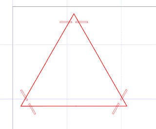
My first order of business was to figure a way to attach the triangles.  One option is to create notches in the corners of each triangle so that I could wrap a rubber band, wire or string (depending on what kind of tension and elasticity I desired) around the notch and connect it to the notches on the other triangles.  I've attempted the diagram below to explain this idea.


Using Inkscape, I drew a triangle and created two thin rectangles as notches.  Since the laser cutter will cut every line shown below in red, it doesn't matter that the rectangles extend past the triangle.


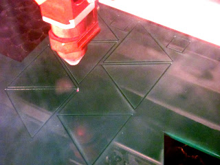
I had just enough time to cut my triangles before class ended.  Here are my first experimental triangles!


07 March 2012

The Engineering Process (5.3.12)

I decided that, instead of cutting my boring carabiner, I would attempt one that looks lie Totoro, from Japanese animator Miyazaki's film My Neightbor Totoro.   In this image, Totoro is the large grey creature who protects and helps the two young girls visit their mother, who is in the hospital.

 
http://www.fanpop.com/spots/the-random-creatures-of-anime/images/13722533/title/totoro-photo

Here you can see the stark contract between my hand-drawn attempt and one drawn with Bezier curves.


My design was cut onto Delrin, but the material began to cool and melt back together, so Totoro's mouth and nose did not punch out.  I'm still pleased with the results, especially for having drawn the design in under 20 minutes.


Here's a screenshot from a video I made of the carabiner being cut!


We made our transition from experimenting within the realm of electrical engineering to considering the general process engineers use to approach problems and find solutions.  Each of these three process represents different theories of engineering and its purpose.  The first process is an older method that neglects to include the product's users in the equation.  This can lead to engineers creating very technically advanced products, but ones that users couldn't easily use or a product that doesn't exactly fulfill a user's need.  The third method is encouraged at Olin because of how it integrates the human side of engineering with the science and math.  The product is always seen in respect to how it affects the user.


Product
Research
Concept
Feasibility
Requirements
System Design
Detail Design
Manufacturing Design
Manufacturing

Iteration
Problem Identification
Requirements
Ideation
Selection
Prototype
Refine

User
Observe
Analyze [personas (or the abstraction of users); framework; areas of opportunity]
Goal [requirements]
Ideate
Represent [create a representation or model]
Codesign [work with users to create the best possible product/function]
Concept [specifications]


Lastly, Oscar gave us a diagram of the process with emphasis on how steps can be repeated many times, and  how the process is more continual rather than having a clear end.


03 March 2012

Designing a Carabiner (1.3.12)

Today we continued working on our carabiners and watched the laser cutter be used for the first time!  Watching the laser cutter was exhilarating; it's amazing how fast the laser moves and with such accuracy!  To create with the laser cutter, we first make our design in Inkscape.  The lines must be red with a "hairline" diameter of .003 inches.  One thing I love about Inkscape is it is easy to switch back and forth between various scales of measurements, such as inches, mm, cm, and pixels.  

I created my design with Bezier Curves, which are lines that can be manipulated by creating nodes along the length of the line. 
http://www.newtechtips.org/bezier-curve-in-c/

 It took some time to get familiar with editing the angles and connecting and disconnecting nodes, but once I figured it out, I really appreciated how simple and professional the Bezier curves look.

Here's my final design for the carabiner, but before I came to this design, I had the hole across from the carabiner opening (on the left in my drawing below).  This meant, however, that stress would be on the opening, which is the weakest part of the carabiner.  I fixed this by moving the hole to the side instead.


I also experimented with how thin the opening of the carabiner should taper.  Would the Delrin be flexible?  Next class I will cut and test my design!